This page will document the main Power Distribution Board for ROSS when the documentation is completed.
Features
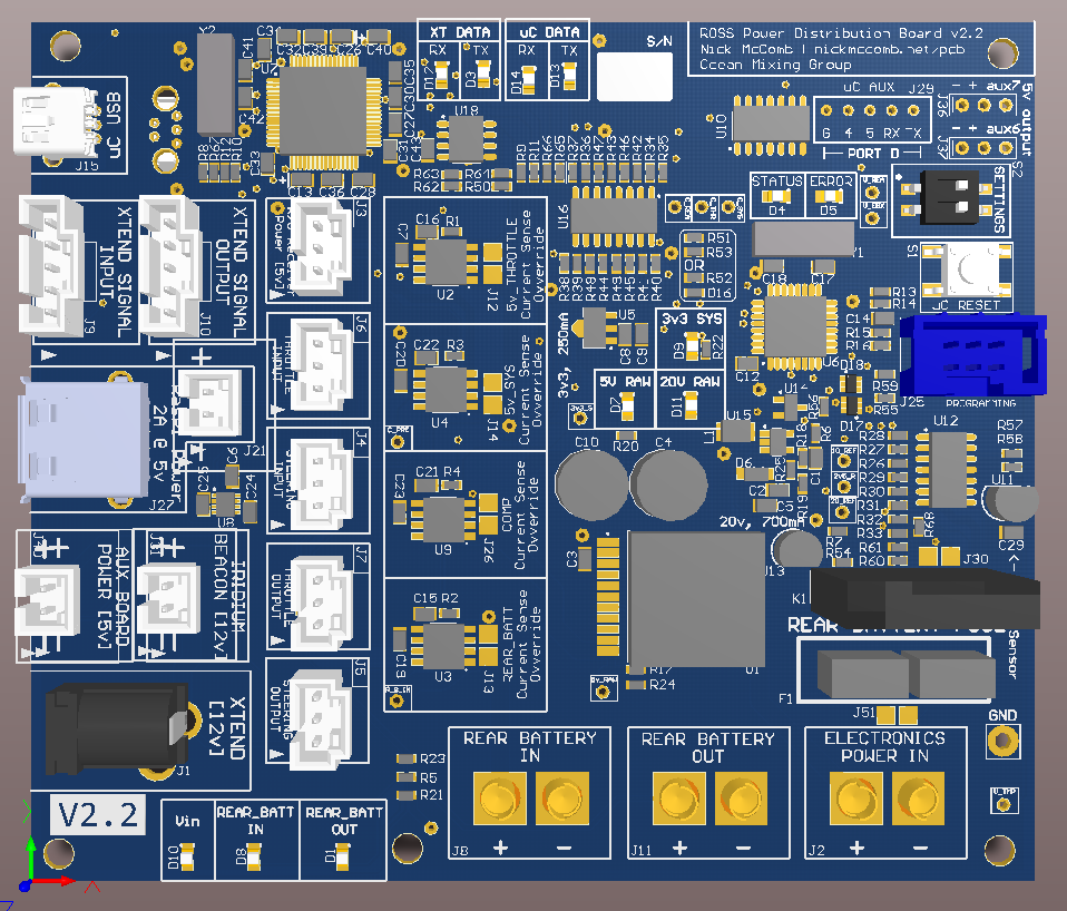
These are the features of the latest version of this board.
- 20v reference
- 10v precision reference
- 5v supply capable of 10A
- 3v3 supply
- 2v5 reference
- 4x current sense
- 5v Throttle servo
- 5v System power
- 5v Computer power
- 12v Steering servo
- Voltage scaling for external current sense (XTend Daughterboard)
- R/C Reciever power output
- XTend Daughterboard power output
- Iridium Location Beacon power output
- Computer power output
- Steering servo power output
- Protection against backfeeding power from all components that might need to be powered separately (Pixhawk, Auxillary board)
- Fuses the alternator power from the engine to the steering servo
- Allows switching on/off of the power to the steering servo while operational
- Logic Level Conversion for the 3v3 outputs of the Pixhawk into 5v PWM signals for throttle and steering
- Voltage rail current sense (using a differential OpAmp multiplier)
- Dual FT2232 UART Chip to support modem communication (see XTend Daughterboard)
- Supports an ATxmega32E5 Microcontroller running at 32MHz
- Supports remote steering servo override (using hardware PWM generation)
- Internal EBox Temperature monitoring
- Current Sensing
- Voltage Sensing
- On/Off Switch passthrough (see internal documentation for more)
Assembly Notes
R24 should be replaced with a 1K if power diodes (D2, D15, D17, D19, D20) are used .
Issues
Issues are available here on GitHub
Schematic
ROSSPowerDistribution Schematic v2.3
Legacy Documents
ROSSPowerDistribution Schematic v2.2
ROSSPowerDistribution Schematic v2.1
ROSSPowerDistribution Schematic v2 (download for 3D PCB render, requires Adobe Reader/DC)
Note: BOM v2 works for board hardware v2 and v2.1